Start with a quick audit of your own habits — the state is saved in this browser:
Internal reference — catch faults before they ruin your measurements
Right after calibration (or after buying the instrument), measure a length of fiber on a spool and record the result. From then on, the same measurement, with the same settings, repeated periodically, is your early-warning system: a large deviation from the original measurement signals instrument damage — usually of the optical port. Regular internal checks are also an argument for extending the recalibration interval. Try it:
✓ result within tolerance — the instrument retains its metrological capability
Calibration — traceability to standards
Metrological verification is performed in laboratories that ensure measurement traceability to national standards. The standards from Table 7 of the handbook: optical power meter — IEC 61315 (calibration of fiber-optic power meters), reflectometer — IEC 61746-1 (calibration of OTDRs for single-mode fiber). Take measurements after the instrument has warmed up, and use the normative documents from that table to build your internal reference.
The protective (sacrificial) attenuator — a fuse for the optical port
In instruments used heavily in the field it pays to keep a protective (sacrificial) attenuator permanently plugged into the output port: it adds barely a few tenths of a dB, yet takes all the wear onto itself. What degrades is the attenuator's endface — which you can replace for pennies — while the instrument's port, whose replacement costs a service visit, stays like new.
A dirty OTDR port = a blind start of the link
Figure 48 of the handbook shows it mercilessly: a dirty connector at the OTDR interface stretches the dead zone from a dozen or so meters to hundreds. Everything within that range — the patch panel, the first connectors, pigtails — disappears from the assessment. Move the slider:
Endface cleanliness is not cosmetics — it is a metrological requirement. Before you start hunting for a fault in the link, make sure you are not measuring your own dirty port.
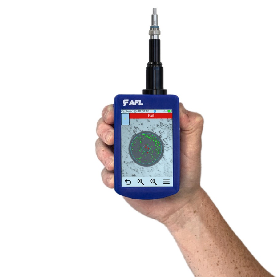 AFL FOCIS Flex3
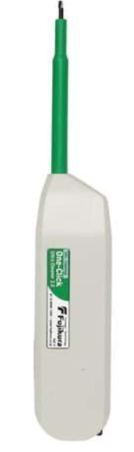 AFL cleaning kits
 AFL light source + power meter
That closes the handbook: safety → inspection and cleaning → attenuation → reflections → reflectometry → good practices. Return to the program.