Return loss (RL) describes the total power returning to the measurement point — the sum of reflections and backscatter from the entire link: RL = −10·log₁₀(P_ret / P_inc). It is positive (the higher, the better). Reflectance describes the strength of the reflection from a single point event: Refl = 10·log₁₀(P_refl / P_inc). It is negative (the lower, the better). Measuring a single event, you get the same magnitude — what differs is the sign and the meaning.
Where reflection comes from
A Fresnel reflection arises at every abrupt change of the refractive index. The worst case is the glass-air interface: up to 4% of the power comes back. See what changes when the ferrules are mated (PC) and when the endface is angle-polished (APC):
the glass-air interface reflects up to 4% of the power straight back to the OTDR
That is why APC connectors are the standard in telecom: the reflection does not disappear — it simply does not return into the core. An 8–9° angle is enough for the reflected ray to leave the fiber through the cladding.
Two measurement methods (IEC 61300-3-6)
Method 1 — OCWR (optical continuous wave reflectometer): closest to the definition, it measures the incident and reflected power directly through a coupler with two detectors. In field practice, ready-made return loss meters are used. Limitations: it cannot spatially separate reflections along the line and it has a limited dynamic range.
Method 2 — OTDR: measures reflectance from the point of reflection with meter-scale resolution and a dynamic range above 75 dB — ideal in the field and on long lines. Where reflections are numerous and close together, the OTDR shows the effective reflectance of their sum.
Measure reflectance with markers
On the trace, reflectance is determined from the pulse height H: Refl ≅ 2H − K′, where K′ depends on the fiber's backscatter coefficient and the pulse width (here: 1550 nm, 100 ns → K′ = 61 dB). The OTDR computes this automatically — but only when the markers stand where they should: A on the backscatter before the event, B on the top of the reflected pulse. Try it:
set the markers and read the result
Four conditions for a good reflectance measurement
The handbook lists them explicitly: 1) a correctly entered backscatter coefficient (the factory value for the given wavelength — without it, K′ lies); 2) the reflected pulse not in saturation — when the peak is clipped, add an attenuator and repeat (check in the simulator above how saturation understates the result); 3) noise-free backscatter — use averaging if needed; 4) short test pulses, which guarantee tall, readable reflections.
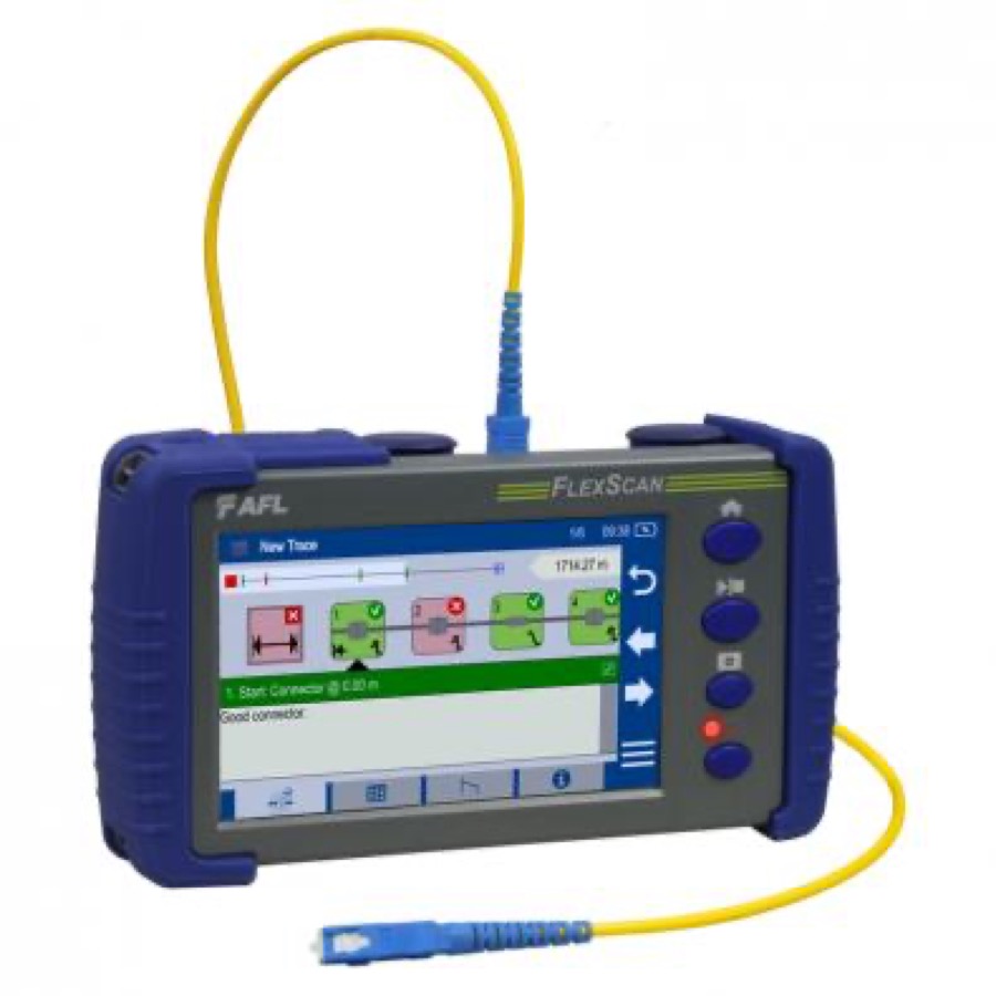
Reflectance without markers: AFL FlexScan FS300
What you just practiced by hand with markers, the pocket-sized FlexScan does automatically — SmartAuto measures the loss and reflectance of every event and grades each one pass/fail on the spot.
See it at INTERLAB →How reflection peaks look in the context of the whole line — and why the APC peak vanishes on a long pulse — you will see in Chapter 5: OTDR Event Analysis.